CIDR

What Is CIDR (Classless Inter-Domain Routing)?

What Is CIDR (Classless Inter-Domain Routing)?

CIDR, which stands for Classless Inter-Domain Routing, is an IP addressing scheme that improves the allocation of IP addresses. It replaces the old system based on classes A, B, and C. This scheme also helped greatly extend the life of IPv4 as well as slow the growth of routing tables.

In this article, we’ll explore how CIDR actually works, as well as provide examples to better demonstrate the concepts explained.

Problems With Class-Based IP Addressing#

The old method of IP addressing came with inefficiencies that exhausted the availability of IPv4 addresses faster than it needed to. The classful routing system included classes A, B, and C:

  • Class A – Over 16 million host identifiers
  • Class B – 65,535 host identifiers
  • Class C – 254 host identifiers

The problem would commonly occur when an organization required more than 254 host machines and therefore would no longer fall into class C but rather class B. This means that the organization would use a class B license even though they had far less than 65,535 hosts. Therefore if an organization only required 2,500 hosts, they would be wasting about 63,000 hosts by holding a class B license which would greatly decrease the availability of IPv4 addresses unnecessarily.

How Does CIDR Work?

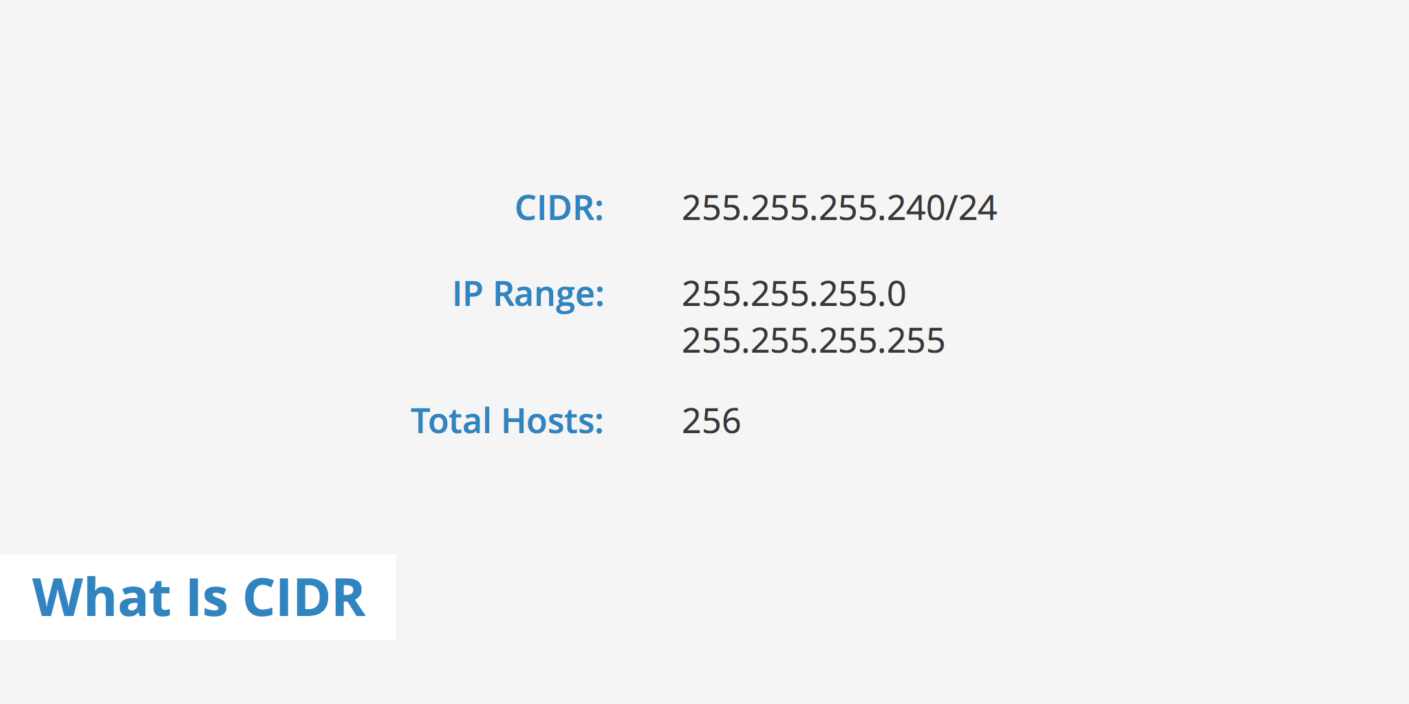
CIDR is based on variable-length subnet masking (VLSM). This allows it to define prefixes of arbitrary lengths making it much more efficient than the old system. CIDR IP addresses are composed of two sets of numbers. The network address is written as a prefix, like you would see a normal IP address (e.g. 192.255.255.255). The second part is the suffix which indicates how many bits are in the entire address (e.g. /12). Putting it together, a CIDR IP address would look like the following:

192.255.255.255/12

The network prefix is also specified as part of the IP address. This varies depending upon the number of bits required. Therefore, taking the example above, we can say that the first 12 bits are the network part of the address while the last 20 bits are for host addresses.

CIDR Calculation tool

Amazon Web Services Best Practices

Design for Failure

Virtual Servers, EC2, and Elastic IP

Amazon Elastic Cloud Compute (EC2) can be thought of as “The Servers in the Cloud”. Regardless of the exact size and quantity, most applications built in the cloud require some servers, and EC2 is the service that provides the servers.

Elastic IP addresses are static IP addresses designed for dynamic cloud computing. An elastic IP address is created at the account level and is not specific to a particular server instance. When a new elastic IP is created within an account, the account controls this access until a choice is made to explicitly release it. Since the elastic IP is not tied to a specific server, but rather to the account, when disaster strikes, one can simply remap the association of the IP from the failed server to a new replacement server. No need to get any data technicians involved, and no need to make any DNS changes.

Designed for failure, lesson #1. Fail over gracefully using elastic IPs. Use elastic IPs to quickly remap and fail over to another set of servers so that web traffic is routed to the new servers. This works great for handling emergencies, but also works well for rolling out new versions of hardware and software.

Regions and Availability Zones

EC2 instances can be launched in one or more geographical regionsEach region is a geographically independent collection of AWS resources. AWS currently operates in 16 geographic regions around the world with more coming online all the time.

Regions are independent of one another, and there is no data replication between them.The customer can decide to launch services in more than one region. 

Even within a region, geographical isolation can be achieved to meet high availability and disaster recovery needs. This is because each region consists of multiple locations called availability zonesAvailability zones are distinct locations that are engineered to be insulated from failures from other availability zones. And provide inexpensive, low-latency network connectivity to other availability zones in the same region. Think of these as distinct data centers that are connected by a fast fiber network.

Designed for Failure: Lesson #2 Utilize multiple availability zones and even multiple regions if required. Availability zones are conceptually like logical data centers.

The Amazon Machine Image

An  Amazon Machine Image (AMI) is basically a packaged environment containing a software stack, along with all the necessary parts to properly set up and boot up an EC2 instance. AMIs are the unit of deployment. AMIs are specified when launching an instance, and as many instances can be launched from an AMI as needed.

Generally, once an EC2 instance is up and running, and configured exactly as needed for a specific application. An AMI is created of that instance. This AMI is then used to easily recreate the instance as many times as needed across multiple availability zones. This can be done programmatically using the API, or the console.

Design for Failure: Lesson #3Maintain an Amazon Image so that you can restore and clone environments very easily across multiple availability zones.

Elastic Load Balancing

An Elastic Load Balancer (ELB) in AWS is a component for balancing network traffic across multiple EC2 instances within multiple availability zones. This allows for greater levels of fault tolerance and high availability in applications. It scales its request handling capacity to meet traffic demands, and does this automatically. 

The Elastic Load Balancer, or ELB for short, has a few key characteristics.

  • It can handle the routing and load-balancing of HTTP, HTTPS, and TCP traffic to your EC2 instance. 
  • It allows health checks to be configured so it can determine whether or not the instances to which it’s routing traffic are healthy and should be used. 
  • It can automatically and dynamically grow and shrink with the demand patterns of an application.

When creating a new ELB, a single CNAME is also created to use for DNS configuration. An interesting thing about this single CNAME is that it does not change even as the ELB scaling is happening. The single CNAME ELB component actually resolves round robin DNS to ELB IP addresses in each availability zone. As traffic increases, AWS adds IP addresses to the ELB’s DNS entry, and continues to round robin requests across the multiple ELBs.

Design for Failure: Lesson #4 Use Elastic Load Balancing to easily distribute an application across multiple resources and availability zones to ensure it remains up and running even when individual components of the application fail.

Cloud Monitoring: CloudWatch

CloudWatch is a resource and application monitoring and alert service that can help provide support for cloud-based applications. CloudWatch allows for the monitoring of resources immediately and automatically, without the need to install or configure any software. It allows visibility into resource utilization performance and traffic load patterns.

It provides tools to gather and graph resource metrics such as CPU utilization, Disk I/O, and network traffic. Alarms can be set when metrics breach certain thresholds. These alarms can then trigger actions, such as sending notifications, or starting processes to automatically handle the issue. By utilizing the API, CloudWatch can also be used to monitor custom metrics generated by custom applications running in the cloud.

Design for Failure: Lesson #5 Utilize Amazon CloudWatch to get more visibility and take appropriate actions in case of hardware failure or performance issues.

Elastic Block Storage

Elastic Block Storage (EBS) are storage resources that are created separately from EC2 instances. Unlike local instance storage, data stored on EBS volumes can live beyond the life of the instance itself. EBS volumes are attached to EC2 instances. Once attached, they can be used like any other block device. Running a file system for data storage is a good example of using this type of storage device. There are two types of EBS volumes: standard volumes and provisioned IOPS volumes.

With EBS, volumes can be created up to one terabyte in size and attached to EC2 instances. Multiple EBS volumes can be attached to a single instance. Point-in-time snapshots of EBS volumes can be created and persisted to Amazon S3. These can then be used to instantiate new volumes.This allows application data to be copied and replicated across AWS regions. The point-in-time snapshot feature is important with regard to designing for failure. Because this allows volumes and data to easily be shared and copied across zones and regions. When created, EBS volumes are stored on S3. Each snapshot is stored incrementally, which means only the blocks that have changed since the last snapshot are saved. When a snapshot is deleted, only the data not needed by any other snapshot is removed. All active snapshots contain all the information needed to restore the volume to the instant at which the snapshot was taken.

When creating a new volume from a snapshot, all of the snapshot data stored in S3 has to be transferred to this newly created volume. The restoring of new volumes from EBS snapshots implements a lazy loading approach. Any data initially being accessed will be prioritized during the transfer.

Design for Failure: Lesson #6Utilize EBS to keep persistent data independent of EC2 instances. And take advantage of the portability and power of  incremental EBS snapshots to replicate data across availability zones and regions.

Manage Relational Database Service

Arguably, one of the most important parts of an application where failure is a big concern is with the persistent data.For many applications, persistent data is stored in a relational database. When this part of an application fails, safe and quick recovery is very important. Amazon Relational Database Service (RDS) provides a way to set up, operate, and scale a relational database in the cloud. RDS speeds the development process by allowing quick access to a full featured database engine without the need to install or configure the software.

Using RDS is straightforward. First, a database instance is created using the web console or the API. When doing so, the engine type is specified. Currently, RDS supports the following engine types, MySQL, Postgres, Aurora, MariaDB, Oracle, and SQL Server. Then the DB instance size is specified including needed memory, storage capacity, and processing power. Once created, CloudWatch can then be set up to monitor the general health of the RDS instances. Unlike with EC2 instances, RDS does not allow direct access to the servers running the database engine.

Design for Failure: Lesson #7Use RDS to simplify relational database security, administration, backups, redundancy, failovers, scalability, and geographical distribution.

Implement Elasticity

Bootstrapping

Bootstrapping refers to creating a sustainable, start up process that can run on its own and in the context of AWS it typically means the process needed to get an application up and running on an EC2 instance. Application instances should be able to come online and then ask questions about who they are and what role they’re supposed to be playing in the application.

All EC2 instance data is available at the same end point over HTTP. On a Linux instance, you can use something like the curl command to get the data. I’ll use curl and list out available metadata options. I can do so right here from the command line. Just type in: 

curl http :// 169.254 .169 .254/latest/meta-data

Running this command returns a listing of all the instance meta-data that’s available on this instance.

For example, say I want to get the instance’s host name. That is the IPv4 DNS Host Name of the instance. I can use the same URL end point and just type in hostname at the end.

curl http :// 169.254 .169 .254/latest/meta-data/hostname; echo $line;

I could also take a look at, for example, the unique AMI id from which this instance was created.

curl http :// 169.254 .169 .254/latest/meta-data/ami-id; echo $line;

Another tool to help with bootstrapping, offered by AWS, is something called Cloud-Init for Linux servers or EC2Config for Windows servers. These allow custom scripts or any shell commands to be specified and run during the instance start up process. This makes it easy to specify server bootstrap needs and they will automatically be run at the appropriate time during the overall instance start up life-cycle.

Implementing Elasticity: Lesson #1:take the time to write the scripts or configure management tools necessary to bootstrap instances. Automating this process will allow you to take advantage of the cloud’s elastic nature.

Autoscaling

Cloud infrastructure can easily scale out, in, up or down,depending on the needs of the system. Scaling out, also referred to as horizontal scaling, is when capacity is added to a system by adding more components or nodes that make up that system. An example of this would be adding more web servers to an application to handle an increase in traffic. Scaling in, also part of horizontal scaling, is simply the opposite of scaling out. It is when capacity is removed from a system by decreasing the number of components or nodes. So, if the number of web servers are reduced, the web server tier has been scaled in. Scaling up, also referred to as vertical scaling, is when resources are added to a single component or node in the system in order to increase its capacity to handle load. An example of this would be increasing the number of CPUs of a web server, or increasing the memory ofa database server. And finally, scaling down, also a form of vertical scaling, is reducing the resources of a single component or node in the system. It’s just the opposite of scaling up. Reducing processing capacity or decreasing memory of a server is scaling down that server. An important thing to understand when building applications in the cloud is that the applications themselves must be built in a scalable way in order to take advantage of a scalable infrastructure. And while the cloud is built to provide at least, in theory, infinite scalability of its resources,the scalability cannot be leveraged if the application itself is not designed in a manner to take advantage of the scalability.

Auto Scaling is a service focused on helping implement elasticity. Increase capacity exactly when load demands, and decrease capacity when load lightens. Always matching the right amount of capacity to meet demand. Auto Scaling is a service provided by Amazon, that makes this easy. Start by defining the conditions on which the application should scale out, or in; based on the number of desired EC2 instances. Then the auto scaling service will add or remove instances when these conditions are met.

With Auto Scaling, a condition can be defined such that, if the CPU utilization rises above 75%, say for more than a minute, the application will automatically scale out, by having two more instances added. One in Zone A, and another in Zone B. This will likely result in lowering the CPU utilization across each server. If at any other time they again rise above 75%, two more instances will be added to accommodate the increase in demand.

Auto Scaling has three Primary Components to it. The first part is what is called the Launch configurationThis defines what to scaleThis is where the EC2 instance size is defined.What AMI to use. What security group and other storage needs. Very much the same as all the configuration settings that need to be defined when launching a new instance. The second part is called an Auto scaling group.This defines where to launch the instances, and also defines limits on the number of instances to launch, should certain events occur. The third component is optional, but is really important to fully implement the real time elasticity. It is called a Scaling policyand it defines the when and under what conditions instant scaling should happen.

The system needs to scale out to handle increase in load, but also needs to scale back in, when load decreases, to keep costs low and avoid waste. 

Implementing Elasticity: Lesson #2. Take advantage of the auto scaling service to greatly simplify the process of automating your scaling. This helps keep application users happy, and business costs minimized.

Scalable Storage: Simple Storage Service (S3) and CloudFront

Amazon offers different storage options to accommodate the different types of data needed to be stored in the cloud. Amazon EFS offers file storageAmazon EBS and EC2 instance storage offers block storage, and Amazon S3 and Glacier offer object storageS3 is an object store. In an object store, objects are stored in a flat organization which are referred to as buckets in S3.

These objects are retrieved by a unique identifier called keys. A key can be any string and can be constructed to mimic hierarchical attributes, meaning that it can sort of be made to look like a directory structure but it should not be confused with one. Objects are really any blob of data, such as backups and archives, log files, videos, images and audio files. This is typically contrasted with a traditional file storage system where files are organized in a directory hierarchy and housed in a central repository of metadata about the files.

In object storage, objects are stored in a non-hierarchical flat, address space which allows for almost endless scalability and very fast object retrieval. Of course, there are some feature trade-offs with object storage compared with file storage. For example, S3 does not natively offer the ability to search across all objects in storage.

S3 is built to be incredibly durable. This is achieved by redundantly storing objects on multiple devices across multiple availability zones in an Amazon S3 region. For non-critical data that may not require these extremely high levels, Amazon also offers reduced redundancy storage, or RRS. This is an option which reduces storage costs and can be used for objects that could easily be reproduced in the event of a failure.

The Glacier storage is like an extension of S3 but is intended for archiving data, for data that will be accessed very infrequently and where retrieval time of several hours is acceptable.

Implementing Elasticity : Lesson #3. Take advantage of the available object storage options in AWS to improve scalability, availability, durability and performance of storing and accessing application asset.

Elastic Beanstalk

Elastic Beanstalk is on the convenience end of the spectrum. Elastic Beanstalk is an example of one of AWS’ fully managed services. It allows you to simply upload an application into AWS, and it takes care of the rest.

It handles provisioning of all the needed resources to run an application in the cloud. It takes care of capacity provisioning, load balancing, auto scaling, and application health monitoring.

Implementing Elasticity: Lesson #4. Consider taking advantage of Elastic Beanstalk to fully manage application deployment and infrastructure in the cloud. And let Beanstalk take care of the scalability, high availability, and high performance requirements.

OpsWorks

OpsWorks is one of several full application management and automation services offered by AWS that sits somewhere in the middle of the spectrum between convenience and control. It allows for management and automation of very customized applications of most any shape or size. OpsWorks has two offerings, AWS OpsWorks for Chef Automate, and AWS OpsWorks Stacks. The focus here is on AWS OpsWorks Stacks. In AWS OpsWorks Stacks, things are conceptually divided into stacks and layers.

In terms of a traditional three tier application architecture, each stack would contain the needed web application, app servers, and database servers to run your application. The servers within these stacks get grouped into roles called layers. A layer is a sort of blueprint for a set of instances specifying information such as the instance settings, resources, and security groups.

High level overview of using OpsWorks. First, a stack is created. Then, one or more layers are defined. Then, the application code to be run and launched into a layer is configured. Then, a Chef cookbook is created and recipes written. These recipes are then associated with specific OpsWorks event lifecycles such as setup, configure, shut down, etc. Then instances are launched into the defined layers. Finally, the applications are deployed onto the servers defined at each application hosting layer.

Implementing Elasticity: Lesson #5. When dealing with an application architecture that is more complex than what Elastic Beanstalk supports, or simply, if more granular deployment and setup control is desired, consider using OpsWorks.

CloudFormation and CloudFormer

Another service offered by AWS to consider when designing application deployment and configuration management processes to best realize designing for elasticity is something called CloudFormation. AWS CloudFormation gives developers and systems administrators an easy way to create and manage a collection of related AWS resources. It allows for the definition of an entire application stack to exist as either a single or set of text based template files.

CloudFormer helps to create a CloudFormation template from an existing stack.

Implementing Elasticity: Lesson #6Use CloudFormation templates to manage and version-control your entire AWS application stack, and easily replicate your full stacks to new environments, new accounts, or new geographical regions.

CodeDeploy

CodeDeploy is not stack or language dependent and is built to work with any existing application files and deployment scripts. The service scales with AWS infrastructure and can be used to deploy to just one or many EC2 instances. One of the advantages to using CodeDeploy is that it’s easy to adopt. If a team already has a defined deployment process, and needs to simply get that working within AWS, CodeDeploy may be a great place to start.

Implementing Elasticity: Lesson #7When dealing with an existing application, with existing steps or scripts for deployment,consider using CodeDeploy as a straightforward method to allow that application to take advantage of elasticity in the cloud.

Decouple Components

Simple Queue Service

The idea behind decoupling components is to build the system such that if any single component of the system were to become unresponsive for some reason, the other components would continue to work as if no failure is happening.Amazon’s Simple Message Queue is a service that helps in this regard. Amazon’s Simple Message Queue Service (SQS), provides an implementation of message queuing software in the cloud. It provides a reliable, highly scalable, and distributed system for passing messages between computers and application components.

With SQS queues in place, rather than communicating directly, the system components use queue buffers to send messages to one another. These queues allow the components to communicate asynchronously, to support concurrency, to remain highly available, and to better handle load and spikes.

Decoupling Your Components: Lesson #1Use SQS as the communication glue to bind independent components together into a fail-safe, scalable, and high performant cohesive application.

Simple Workflow Service (SWF)

Another service in the AWS Library that provides a means to achieve decoupling components is called Simple Work Flow (SWF). This service is built to help define, manage, and coordinate the tasks that make up a given business workflow. It also handles things such as the overall state of the system. It is intended to deliver all the boilerplate and often complex code needed to manage the dependencies across activities defined in a business workflow process.

A simple ecommerce order process is a common example of a workflow used when introducing the concept of workflow. The workflow begins when a customer places an order, and consists of four tasks. First, ensure the order is valid. If the order is valid, then charge the customer for the order. If the payment is successful, proceed to ship the order and if the order is shipped, have the order saved as complete.

When creating a workflow with SWF, SWF takes care of the task management, but the application developer configures how the workflow makes decisions about how to proceed once one or more of the workflow tasks has been completed.

These parts are called deciders. The decider helps put the flow in workflow. It responds to results from tasks that have been completed and makes the decisions about what to do next based on configured business rules, and these decisions are triggered based on events assigned by SWF. The other primary piece of the workflow that must be created is the actual carrying-out of the defined task.

These are referred to as activity workers. An activity worker carries out the work assigned by SWF tasks. The decider is responsible for scheduling the work carried out by the activity workers, and these activity workers can be distributed and run from anywhere.

SWF can really help to simplify the coordination and complexities of more sophisticated, distributed, and even parallel workflows. And as all the activity workers are self-contained and independent from one another, SWF can help create complex workflows with decoupled components.

Decoupling components: Lesson #2. Consider using SWF to help with more complex workflows, and to help keep components independent from one another.

Simple Notification Service

Amazon Simple Notifications Service (SNS), provides a simple way to notify applications or people from the cloud, by creating topics and using a publish-subscribe protocol. SNS allows messages to be published from within an application or directly from the console, and have those messages be delivered to subscribers via several protocols. Messages are first published to a centralized topic, then subscribers to the topic receive the messages.

SNS supports different protocols, with email being one. Another protocol it supports is SMS text messages. SNS allows us to set up a push notification as a means for application components to communicate. This is one way in which SNS differs from Amazon SQS. SQS requires an application to constantly poll for new messages on the queue. This is commonly referred to as a pull approach. SNS allows us to introduce a push approach as a solution to keep system components independent and decoupled.

Decoupling components: Lesson #3. Take advantage of the SNS push approach to help with communication between system components, as well as having those components work in parallel for highly efficient and scalable systems.

Scalable No SQL data store: DynamoDB

DynamoDB is a NoSQL, non-relational, schema-less database service that has been built from the ground upto deliver low latency, high performance, and high throughput. It scales automatically to meet application throughput requirements.Instead of using traditional hard drives, the data is stored on solid-state drives which provides very fast data access.

Decoupling Components: Lesson $4Keep the scalable server components of applications as stateless as possible, and when session state is needed, store this state in a centralized storage using DynamoDB.

Optimize For Performance


Incident Severity

A standard classification for incidents gives all involved a common language to describe what’s going on.

Why bother? And why have so many levels?

I think it’s important to track the kinds of things engineers are being woken up for and to deliver a response that’s suited to the problem.

severity levels defined

  • Sev1 Complete outage
  • Sev2 Major functionality broken and revenue affected
  • Sev3 Minor problem, bug
  • Sev4 Redundant component failure
  • Sev5 False alarm or alert for something you can’t fix

Whenever the pager goes off, it’s an incident.  All these kinds of incidents need different responses.

Classifying them might appear difficult.  But it isn’t really.  Here’s an automotive example.

  • Your car runs out of fuel. = Sev1
  • Your clutch is busted. You can drive but only in first gear. = Sev2
  • One headlight has blown. = Sev3
  • You find your car has a flat tyre. You change the tyre and drive to your destination. = Sev4
  • The low fuel warning light is stuck on even though you just filled the tank. = Sev5

Everyone in your organization should be trained to use this terminology.  Especially front line support people.  They should feel comfortable saying “Guys we have a Sev1, call the on-call engineer immediately” if that’s the case.

Track the frequency of these every week.  Put ’em in a spreadsheet.  Make sure people know what’s going on.  If you’re getting alerts for Sev4 and Sev5, you need to change something to stop them.  Sleep is precious. We have !SPOF for a reason.  Some things are best left till morning to fix.  Perhaps the thresholds are set wrong? Don’t alert on something you can’t fix.  That’s a deeper problem that you need to address as an organization, not the responsibility of the guy on call.


There are 4 different levels of disaster severity related to the contact center, and each level impacts the experience you deliver to your customers. These levels are SEV1, SEV2, SEV3, and non-production defect. SEV1 is the most serious level with non-production being the most mild.

SEV1: Critical Impact/System Down

A SEV1 defect is a production outage. This is where the production system has ceased to operate, and there is no workaround. There are several different ways that a contact center can experience a SEV1 outage. An example is an error in the IVR, such as a prompt not loading, that prevents callers from being able to complete tasks within the IVR, resulting in a significant number of additional calls getting through to the agents. The errors can also involve agent systems, such as the CRM system failing, making it impossible for agents to access customer records and serve customers effectively.

SEV2: Significant Impact

A SEV2 defect refers to defects that affect production, but workarounds are possible. A SEV2 disaster, compared to a SEV1, is not a production outage but still affects the customer experience. For example, the CTI might misroute calls, resulting in agents having to manually transfer calls. Ultimately the customer is served, but there’s a not insignificant negative impact to the customer experience.

SEV3: Minor Impact

A SEV3 defect also impacts production systems. Customers and agents are able to accomplish tasks, but experience nuisances and inconveniences. An example of a SEV3 in a contact center is when audio quality is poor, requiring the customer and agent to repeat themselves, but ultimately, they are able to accomplish their tasks. In terms of your CX, these aren’t critical, but are the CX equivalent of death by a thousand paper cuts.

Non-production

Non-production defects are found before systems are put into production. An example of a non-production issue would be a Disaster Recovery failure identified during a load test. The earlier in the development cycle that you are able to identify defects, the better. And, of course, keeping them out of the production environment is critical to providing a good CX.

It is important for organizations to minimize the risk of these different levels of disasters. Each level provides its own challenges financially and to company resources. Not only will it cost the company time and money to fix the issue, but it can cost them customers as well. Customer Experience is where customers are won and lost. Help make every customer experience a win by using Cyara’s suite of products to ensure customer satisfaction one experience at a time

NetBIOS

NetBIOS over TCP/IP (NBT, or sometimes NetBT) is a networking protocol that allows legacy computer applications relying on the NetBIOS API to be used on modern TCP/IP networks.

NetBIOS was developed in the early 1980s, targeting very small networks (about a dozen computers). Some applications still use NetBIOS, and do not scale well in today’s networks of hundreds of computers when NetBIOS is run over NBF. When properly configured, NBT allows those applications to be run on large TCP/IP networks (including the whole Internet, although that is likely to be subject to security problems) without change.

NBT is defined by the RFC 1001 and RFC 1002 standard documents.

NetBIOS provides three distinct services:

  • Name service for name registration and resolution (ports: 137/udp and 137/tcp)
  • Datagram distribution service for connectionless communication (port: 138/udp)
  • Session service for connection-oriented communication (port: 139/tcp)

DNS MX records

source

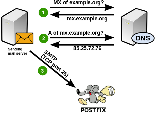
So now you have your working mail server. But how do emails find you? The answer lies in the most important service on the internet: DNS. Assume that you are the owner of the gmail.com domain. And a mail server somewhere on the other end of the internet wants to send an email to john@example.org. What the other mail server needs to do is find out which server on the internet it will have to establish an SMTP connection to in order to deliver the email. Let’s reiterate how that happens:

ispmail-jessie-bigpicture-mx

The remote server queries its DNS server for the MX (Mail eXchanger) record of the “example.org” domain. If no MX record was found it tries again and asks for A (address) records. Let’s run a query for a real domain to get an idea:

$> host -t MX gmail.com
gmail.com mail is handled by 10 alt1.gmail-smtp-in.l.google.com.
gmail.com mail is handled by 20 alt2.gmail-smtp-in.l.google.com.
gmail.com mail is handled by 30 alt3.gmail-smtp-in.l.google.com.
gmail.com mail is handled by 40 alt4.gmail-smtp-in.l.google.com.
gmail.com mail is handled by 5 gmail-smtp-in.l.google.com.

So as a result we get 5 different MX records. Each of them consists of a priority and the host name of the mail server. A mail server would pick the entry with the highest priority (=the lowest number) and establish an SMTP connection to that host. In this example that would be the priority 5 server gmail-smtp-in.l.google.com. If that server could not be reached then the next best server with priority 10 would be used and so on. So all you have to do in your own DNS zone is add an MX entry pointing to your mail server. If you want to run a backup mail server (which is outside of the scope of this tutorial) then you can add a second entry with a an equal or lower priority.

A mistake some people make is using an IP address in MX records. That is not allowed. An MX record always points to a host name. You will have to add an A record for your MX record to point to the actual IP address of your mail server.

(In the above example it is very unlikely that a mail server will ever have to use the server with priority 40. Adventurous system administrators can add such a low-priority entry and see who connects to it. An interesting observation is that spammers often try these servers first – hoping that it is just for backup purposes and less restrictive than the main server. If you see someone connecting to the lowest-priority address first without having tried a higher-priority mail server then you can be pretty certain that it’s not a friend who’s knocking at your door.)

Fallback to A entries

It’s always best to explicitly name mail servers in the MX records. If you can’t do that for whatever reason then the remote mail server will just do an A record lookup for the IP address and then send email there. If you just run one server for both the web service and the email service then you can do that. But if the web server for your domain is located at another IP address than your mail server then this won’t work.

BeyondCorp

https://cloud.google.com/beyondcorp/

Today, none of Google’s employee-facing applications are on a virtual private network. They all have public IP addresses.

The company feels this approach, which it has dubbed BeyondCorp, is the “new cloud model,” for doing cloud security, asserted Neal Mueller, head of infrastructure product marketing at Google, who gave a presentation on this approach at the O’Reilly Security conference, held recently in New York.

This model can be fall under a number of rubrics in the security community, including “zero-trust” or “perimeter-less” security. It is the opposite of the traditional approach of security, which Mueller described as “the castle” approach, in which a strong firewall is used to set off an internal network that can only be accessed by way of a virtual private network (VPN).

The problem with the “castle” approach is that once the perimeter is breached, the entire internal network, and all the associated applications, are at risk. “Do not trust your network. It is probably already owned,” added Max Saltonstall, a Google program manager for corporate engineering, who also participated in the presentation. Phishing, man-in-the-middle, SQL Injection attacks all find fertile ground on VPNs.

Plus, a VPN was cumbersome to use, and slowed performance, especially for overseas workers. And it is no walk in the park for admins either. To set up a new user, the admin would typically have to configure the cloud network, along with setting up the IPSec rules and firewall rules, the VPN. This is followed by a lot of testing.

At Google, “we embraced the fact that walls don’t work,” Mueller said. “Rather than have a VPN around all this infrastructure, we decided to get rid of the walls entirely.”

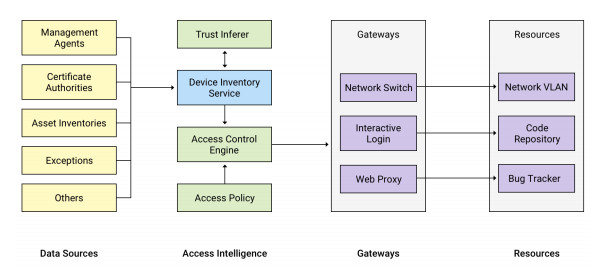
Google’s approach involves comprehensive inventory management, one that keeps track of who owns which machine in the network. A Device Inventory Service collects a variety of live information about each device from multiple system management sources, such as Active Directory or Puppet.

Authentication is then based on a set of “Trust Tiers” represent levels of increasing sensitivity. Employees get the appropriate level of access regardless of what device they are using or where in the world they are logging in from. Lower levels of access require less stringent checks on the device itself.

“The access is granted based on context: Who are you? Have you authenticated in a strong way? What are you using? What do I know about your device?” Saltonstall summarized.

The network itself is unprivileged. For identity management, the company uses security keys, which are much harder to forge than passwords and are tied to the individual users themselves. Each work device has a certificate issued by Google. Encryption across the network is done through TLS (transport layer security), which is terminated at the access proxy.

All the corporate resources are behind this uber-reverse proxy. Based on a decision provided by its “trust engine,” the proxy makes the decision of whether or not to provide access to the desired application. If permissions are in place, according to the tiered trust model, it forwards the requests to the application, along with the security credentials. The applications themselves are routinely checked for breaches by vulnerability scanners.

Amazingly, Google was able to shift all of its employees, including remotes ones, over to this new model, with minimal disruption, Saltonstall said.

To prepare for a transparent shift, which started in 2013, the migration team recorded all the actions that Google employees did on the old network, then rerun a simulation of the traffic on the new network. This monitoring gathered about 80TB a day (The model benefited the fact that all of Google’s internal applications are already on the Web).

“If you play back the current traffic on the new network, you can see what will break,” Saltonstall said. This lets the team identify those end-services that weren’t fully compliant yet, as well as identified users who could seamlessly switch over to the new network.

This approach has some good additional benefits, Saltonstall said. Provisioning Chromebooks for new employees is a minimal processing, taking no longer than 90 seconds worth of configuration settings.

With the “BeyondCorp” approach, “You are taking operation problems, and turning them into engineering problems, and then engineer them away,” Saltonstall said. “All the frustrating, boring human grunt-work becomes automated.”

rsync

source

Introduction

Rsync, which stands for “remote sync”, is a remote and local file synchronization tool. It uses an algorithm that minimizes the amount of data copied by only moving the portions of files that have changed.

What Is Rsync?

Rsync is a very flexible network-enabled syncing tool. It can also refer to the network protocol developed to utilize this tool. When we reference rsync in this guide, we are mainly referring to the utility, and not the protocol.

Due to its ubiquity on Linux and Unix-like systems and its popularity as a tool for system scripts, it is included on most Linux distributions by default.

Rsync copies files either to or from a remote host, or locally on the current host (it does not support copying files between two remote hosts).

There are two different ways for rsync to contact a remote system: using a remote-shell program as the transport (such as ssh or rsh) or contacting an rsync daemon directly via TCP. The remote-shell transport is used whenever the source or destination path contains a single colon (:) separator after a host specification. Contacting an rsync daemon directly happens when the source or destination path contains a double colon (::) separator after a host specification, OR when an rsync:// URL is specified (see also the lqUSING RSYNC-DAEMON FEATURES VIA A REMOTE-SHELL CONNECTIONrq section for an exception to this latter rule).

Basic Syntax

The basic syntax of rsync is very straightforward, and operates in a way that is similar to ssh, scp, and cp.
We will create two test directories and some test files with the following commands:

    cd ~
    mkdir dir1
    mkdir dir2
    touch dir1/file{1..100}

We now have a directory called dir1 with 100 empty files in it.We also have an empty directory called dir2.

To sync the contents of dir1 to dir2 on the same system, type:

    rsync -r dir1/ dir2

The -r option means recursive, which is necessary for directory syncing.

We could also use the -a flag instead:

    rsync -a dir1/ dir2

The -a option is a combination flag. It stands for “archive” and syncs recursively and preserves symbolic links, special and device files, modification times, group, owner, and permissions. It is more commonly used than -r and is usually what you want to use.

An Important Note

You may have noticed that there is a trailing slash (/) at the end of the first argument in the above commands:

$ rsync -a dir1/ dir2

This is necessary to mean “the contents of dir1“. The alternative, without the trailing slash, would place dir1, including the directory, within dir2. This would create a hierarchy that looks like:

~/dir2/dir1/[files]

Always double-check your arguments before executing an rsync command. Rsync provides a method for doing this by passing the -n or –dry-run options. The -v flag (for verbose) is also necessary to get the appropriate output:

rsync -anv dir1/ dir2
sending incremental file list
./
file1
file10
file100
file11
file12
file13
file14
file15
file16
file17
file18
. . .

Compare this output to the output we get when we remove the trailing slash:You can see here that the directory itself is transferred.

rsync -anv dir1 dir2
sending incremental file list
dir1/
dir1/file1
dir1/file10
dir1/file100
dir1/file11
dir1/file12
dir1/file13
dir1/file14
dir1/file15
dir1/file16
dir1/file17
dir1/file18
. . .

How To Use Rsync to Sync with a Remote System

Syncing to a remote system is trivial if you have SSH access to the remote machine and rsync installed on both sides. If you need to set up SSH keys, click here.

Once you have SSH access verified on between the two machines, you can sync the dir1 folder from earlier to a remote computer by using this syntax (note that we want to transfer the actual directory in this case, so we omit the trailing slash):

$ sync -a ~/dir1 username@remote_host:destination_directory

This is called a “push” operation because it pushes a directory from the local system to a remote system. The opposite operation is “pull”. It is used to sync a remote directory to the local system. If the dir1 were on the remote system instead of our local system, the syntax would be:

$ rsync -a username@remote_host:/home/username/dir1 place_to_sync_on_local_machine

Like cp and similar tools, the source is always the first argument, and the destination is always the second.

Useful Options for Rsync

Rsync provides many options for altering the default behavior of the utility. We have already discussed some of the more necessary flags.

If you are transferring files that have not already been compressed, like text files, you can reduce the network transfer by adding compression with the -z option:

$ rsync -az source destination

The -P flag is very helpful. It combines the flags –progress and –partial. The first of these gives you a progress bar for the transfers and the second allows you to resume interrupted transfers:

$ rsync -azP source destination

Output

sending incremental file list
./
file1
           0 100%    0.00kB/s    0:00:00 (xfer#1, to-check=99/101)
file10
           0 100%    0.00kB/s    0:00:00 (xfer#2, to-check=98/101)
file100
           0 100%    0.00kB/s    0:00:00 (xfer#3, to-check=97/101)
file11
           0 100%    0.00kB/s    0:00:00 (xfer#4, to-check=96/101)
. . .

If we run the command again, we will get a shorter output, because no changes have been made. This illustrates rsync’s ability to use modification times to determine if changes have been made.

$ rsync -azP source destination

Output

    sending incremental file list
    sent 818 bytes received 12 bytes 1660.00 bytes/sec
    total size is 0 speedup is 0.00

We can update the modification time on some of the files and see that rsync intelligently re-copies only the changed files:

$ touch dir1/file{1..10}

$ rsync -azP source destination

Output

    sending incremental file list
    file1
               0 100%    0.00kB/s    0:00:00 (xfer#1, to-check=99/101)
    file10
               0 100%    0.00kB/s    0:00:00 (xfer#2, to-check=98/101)
    file2
               0 100%    0.00kB/s    0:00:00 (xfer#3, to-check=87/101)
    file3
               0 100%    0.00kB/s    0:00:00 (xfer#4, to-check=76/101)
    . . .

In order to keep two directories truly in sync, it is necessary to delete files from the destination directory if they are removed from the source. By default, rsync does not delete anything from the destination directory.

We can change this behavior with the –delete option. Before using this option, use the –dry-run option and do testing to prevent data loss:

$ rsync -a –delete source destination

If you wish to exclude certain files or directories located inside a directory you are syncing, you can do so by specifying them in a comma-separated list following the –exclude= option:

$ rsync -a –exclude=pattern_to_exclude source destination

If we have specified a pattern to exclude, we can override that exclusion for files that match a different pattern by using the –include= option.

$ rsync -a –exclude=pattern_to_exclude –include=pattern_to_include source destination

Finally, rsync’s --backup option can be used to store backups of important files. It is used in conjunction with the --backup-dir option, which specifies the directory where the backup files should be stored.

$ rsync -a –delete –backup –backup-dir=/path/to/backups /path/to/source destination

Conclusion

Rsync can simplify file transfers over networked connections and add robustness to local directory syncing. The flexibility of rsync makes it a good option for many different file-level operations.

A mastery of rsync allows you to design complex backup operations and obtain fine-grained control over what is transferred and how.
RFC 1918

Request for Comment 1918 (RFC 1918), “Address Allocation for Private Internets,”is the Internet Engineering Task Force (IETF) memorandum on methods of assigning of private IP addresses on TCP/IP networks.

Along with NAT (network address tunneling), RFC 1918 facilitates expansion of the usable number of IP addresses available under IPV4, as a stopgap solution to prevent the exhaustion of public IPs available before the adoption of IPV6. It’s not necessary to register private IPs with a Regional Internet Registry (RIR), which simplifies setting up private networks.

RFC 1918 was used to create the standards by which networking equipment assigns IP addresses in a private network. A private network can use a single public IP address. The RFC reserves the following ranges of IP addresses that cannot be routed on the Internet:

  • 10.0.0.0 – 10.255.255.255 (10/8 prefix)
  • 172.16.0.0 – 172.31.255.255 (172.16/12 prefix)
  • 192.168.0.0 – 192.168.255.255 (192.168/16 prefix)

IP addresses within these ranges can be assigned within a private network; each address will be unique on that network but not outside of it. Private IP addresses can’t be communicated with directly by external computers because they are not globally unique and, as such, not addressable on the public Internet.

Computers on the inside of the network can communicate with the Internet through NAT.  NAT translates an IP address used within one network to a different IP address known within another network. Typically, a company maps its local inside network addresses to one or more global outside IP addresses and unmaps the global IP addresses on incoming packets back into local IP addresses.